

Thermal Energy Storage (TES) – Subsystem & Pre-Conditioning Strategies
Intermediate result from partners IDIADA, CRF, DNTS, HUTCH and Stellantis.
Result has been achieved on 16 October, 2019 in month 24 of the project.
Short introduction
This article is intended at providing an overview of the development of:
- Preconditioning strategies aimed at optimizing the operating conditions at vehicle level (cabin & powertrain),
- And of a high energy density Thermal Energy Storage (TES) subsystem, including the investigation and development done on innovative materials that are able to reduce the thermal losses and to store the thermal energy as long as possible.
Objective
Based on the vehicle level requirement and specifications, use cases and packaging study defined in Result category 1 and 5, the main objectives were:
- to investigate powertrain and passenger comfort preconditioning strategies of the addressed vehicle, when driving or not, in order to provide additional benefit for systems start-up in cold-starts situations, even at moderate temperatures.
- to investigate and develop a thermal energy storage subsystem of 3 MJ energy density, based on the latent heat accumulation of Phase Changing Materials (PCM), for capturing otherwise wasted thermal energy from both preconditioning phases, when the vehicle is plugged to the power grid and when remaining heat fluxes that would otherwise be lost; for use by vehicle thermal comfort, particularly at start-up. The TES component will be added to the usual coolant loop of the vehicle.
Research
To address the DOMUS objective of “significantly increase electrical vehicle (EV) efficiency through an optimization of the operating condition (mainly start-up) of the vehicle thermal management in a gradual way so as to avoid high-consuming and abrupt temperature change requests that would have a negative impact on the vehicle’s driving range”; a TES subsystem component, combining sensible (specific) heat effect and latent heat effect at a phase change, Figure 1, was developed and included in the active preconditioning strategies.

Figure 1. Thermal energy stored combining sensible (specific) heat effect and latent heat effect at a phase change.
Different aspects like thermal stratification, PCM materials, encapsulation and thermal insulation were focused:
- to optimize the charging and discharging qualities (sensible heat has less energy stored but is released quicker; latent heat has more energy stored but released in more time).
- and to improve the overall heat transfer of the modern thermal energy storage framework.
How has this been done?
A summary of the development of the TES subsystem, divided in several subtasks, is presented:
- Mainly two types of materials have been investigated and implemented:
- First, a family of materials based on PCM with adequate thermal properties as a high thermal conductivity (when macro-encapsulated) and a very strong capacity for energy absorption.
- Second, a super thermally insulating material based on organic aerogel technology with very low thermal conductivity (λ<7mW.m-1.K-1). This super thermally insulating material has been used in a double wall to insulate the TES subsystem.
- Simulations based on the comprehensive thermal energy storage model were performed to investigate the influence of the different ambient conditions and of the time on the thermal quantities: virtual assessment using Simcenter Amesim simulation platform.
- Manufacturing.
- Tests and validation: several conditions have been selected to test the TES subsystem. Dynamic charge and dynamic discharge have been carried out with a set temperature and different static discharges in order to quantify the thermal losses.
Implementation
According to the test scenarios defined in WP1, EV range reduction due to electric heaters for the cabin and the battery thermal management at cold conditions, and the addressed vehicle (Fiat 500e) standard layout, the thermal energy storage component was added to the Hot Side Coolant loop of the Fiat500e standard layout (Figure 2), thereby providing a new improved thermal management DOMUS layout (Figure 3), and used for heating purposes of the cabin.
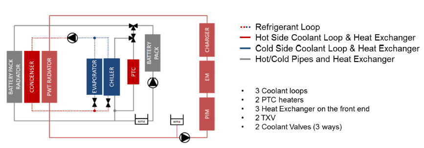
Figure 2. Fiat 500e Thermal system standard layout.
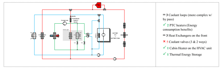
Figure 3. Fiat 500e Thermal system DOMUS layout with a Thermal energy storage (TES) on the Hot Side Coolant Loop.
The TES component has been designed according with the thermal storage packaging studies and will be integrated into the Fiat 500e demo. car underbody (rear area) as shown in Figure 4 .
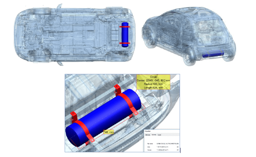
Figure 4. Thermal storage (in blue) rear installation area from bumper and battery.
Result
Thermal Energy Storage Component
The overall storage tank is comprised of an AISI 304 L inner casing, a PA 12 HST [5] outdoor casing and is of 749 mm in height and 200 mm in diameter.
In addition, the whole TES is thermally insulated with an innovative VIP thermal protection of 14 mm thickness based on organic aerogel technology with very low thermal conductivity λ<7[mW/(m.K)].
Suitable CPVC piping and fittings were done of the complete set up so to prevent the leakage problem.
The packed bed is randomly packed with 2287 PCM encapsulated warhead capsules (Aluminum / 19 mm in height and 15 mm in diameter) having a unique RUBITHERM®RT pure phase change material in them, RT35HC (Paraffin) whose melting temperature is about 35 degC. Each capsule was filled with 1,2 g approximately of PCM. Total of 2.7 kg PCM was used to fill all the capsules.
The features of the packed-bed and materials used throughout the system are illustrated in Table 1. Materials with high thermal conductivity has be chosen.
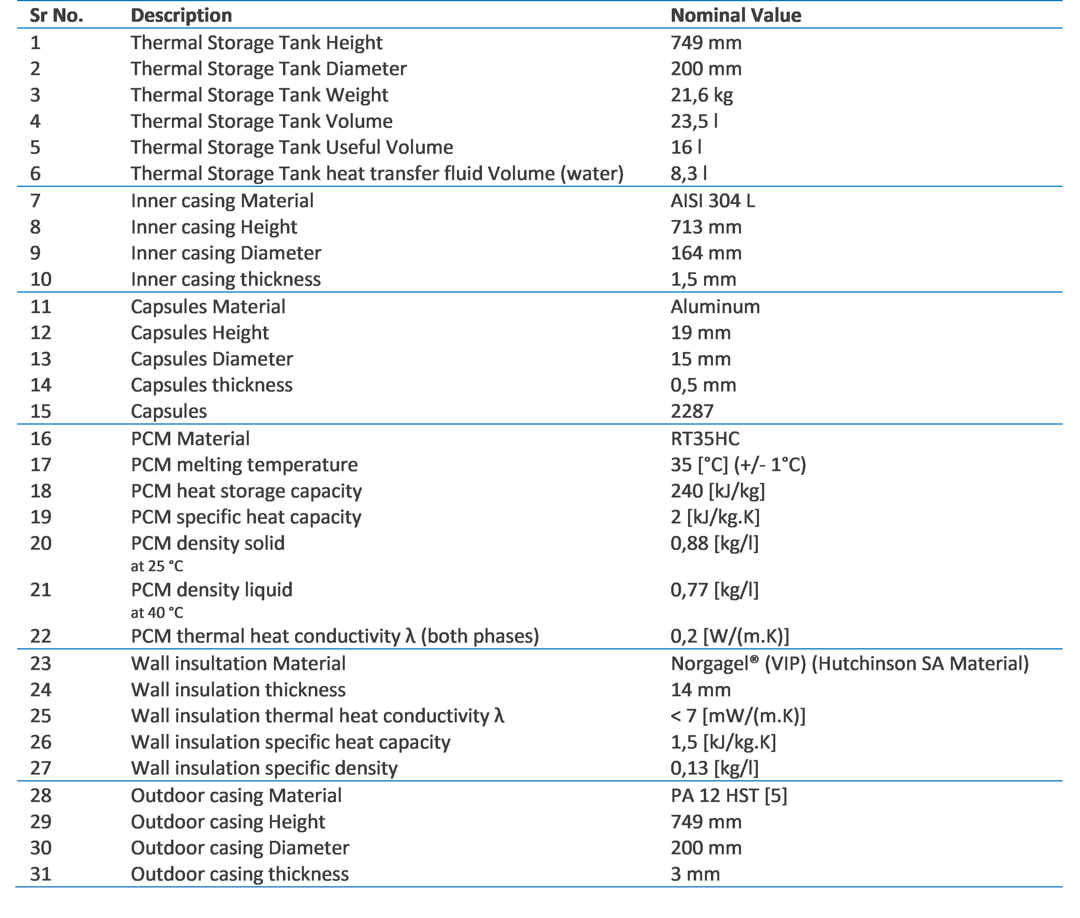
Table 1. Characteristics of the Thermal Energy Storage.

Figure 6. Characteristics & Design of the Thermal Energy Storage developed within DOMUS project.
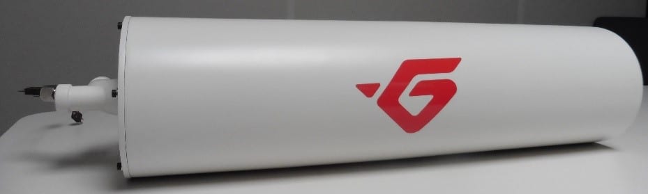
Figure 7. Final & Manufactured Thermal Energy Storage developed within DOMUS project.
Tests results
The initial results lead to following conclusions:
- The thermal energy storage is a feasible solution to significantly store a high amount of thermal energy, from 2.1 MJ to 3.9 MJ at low (–16°C) ambient temperatures,
- The thermal energy storage up to 0.75 kWh allows getting sufficient heating power after a long parking of 15 hours reinforcing the use of the TES at start-up,
- Heating power above 4kW is maintained for at least 2 minutes during discharge,
- Electric energy consumption for the heating mode of the cabin could be significantly reduced with the new system layout and thermal energy storage (by limiting the use of electric heater), providing comparable climatic comfort to the passengers,
- Electric heaters probably cannot be removed but can be downsized
- The potential of using waste heat and a heat storage to increase the vehicle range,
- The experimental results will be beneficial for the fitting of the simulation’s model.
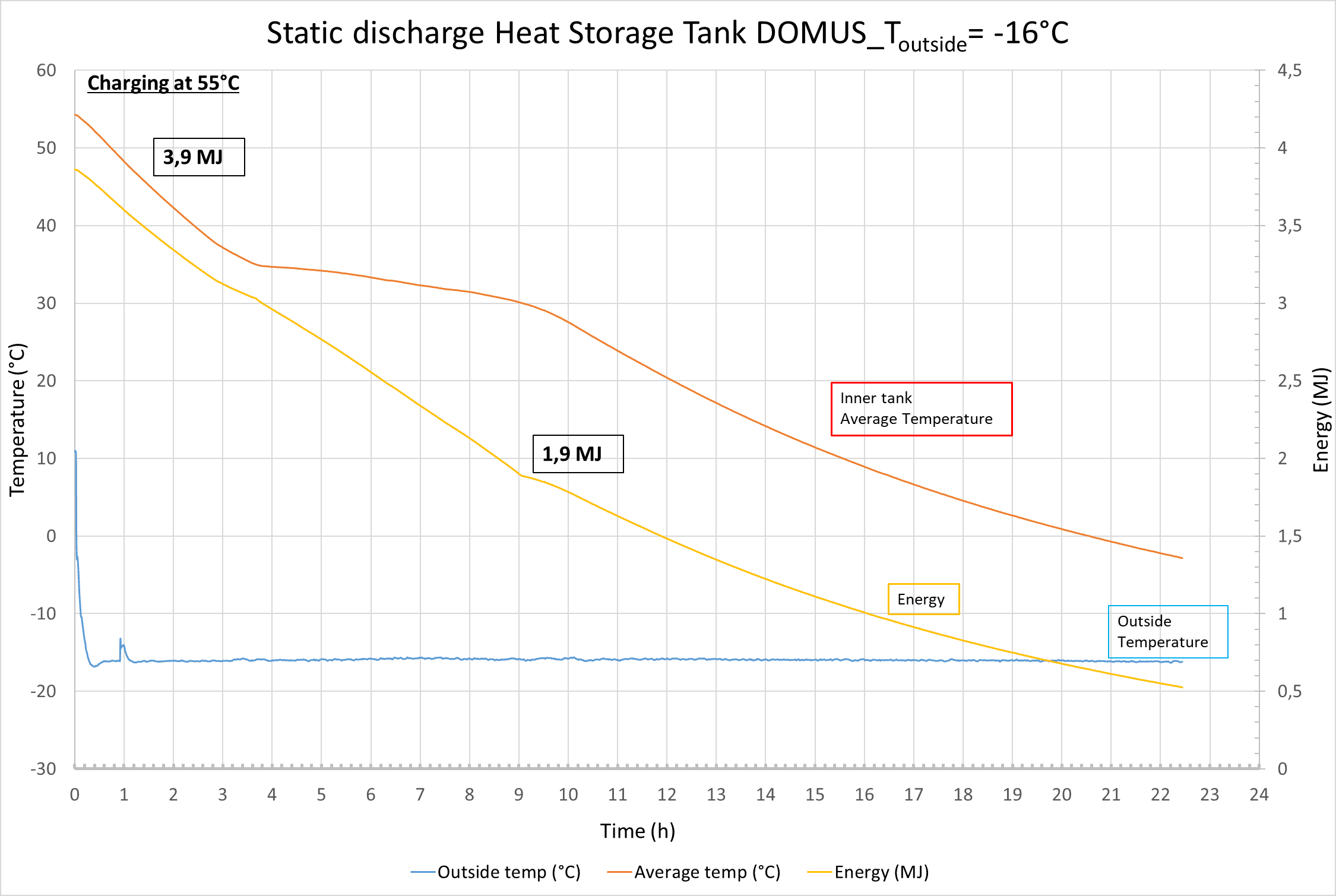
Figure 8: Evolution of the Thermal storage heat transfer fluid Temperature and of the Thermal Energy in function of the time @ Tamb=2.5°C for static discharge.
The operating modes related to the development of the TES subsystem are presented below:
- Charging operating modes for capturing wasted thermal energy from both preconditioning phases and driving running phases:
- when the vehicle is plugged to the power grid from the battery and / or from the electric heaters,
- when remaining heat fluxes that would otherwise be lost; from the e-powertrain and / or from the battery and / or from the cabin (using recycling HVAC system mode).
- Discharging operating modes for retrieving the previous captured and wasted thermal energy during both preconditioning phases and driving running phases:
- to the cabin (via a cabin heater) and / or to the battery and / or to the e-powertrain when the vehicle is plugged to the power grid (see section 2 for more details),
- to the cabin and / or to the battery and / or to the e-powertrain when the vehicle is in running phases at start-up.
for:
- decreasing the energy consumption for a set of scenarios (vs baseline without thermal energy storage subsystem / vs base without preconditioning),
- increasing the thermal comfort perception for a set of scenarios – time/temperature (vs baseline without thermal energy storage subsystem / vs base without preconditioning),
- increasing the driving range for a set of scenarios (vs baseline without thermal energy storage subsystem / vs base without preconditioning).
The overall objective of those discharging operating modes is to avoid the use of the electric heaters (or at least to reduce the use and the electrical energy consumption of the electric heaters). At very extreme cold conditions electric heaters probably cannot be removed but can be downsized.
Also, those functionalities allow to reach the set temperature in the cabin faster than a conventional HVAC system using a simple hot side coolant loop with back up provide by electric heaters.
What will the results be used for?
It will be shown through WP6 that despite a low amount of waste heat from the e-powertrain, and a low thermal storage density, the combination of advanced controlling strategies / preconditioning strategies and a thermal energy storage subsystem leads to:
- a considerable reduction of the energy consumption,
- a considerable increase of the vehicle range,
- allows reaching the cabin target temperature faster than a conventional HVAC system.
The experimental results will be beneficial for the fitting of the simulation’s model.
What is the impact?
Advanced and innovative thermal-management subsystems through different solutions. That is how the thermal energy storage subsystem can improve coolant, refrigerant and passenger compartment temperatures regulation and power consumption by better regulating the thermal energy process.
The thermal energy storage associated to preconditioning strategies aims to radically change the management of start-up procedures for Electric Vehicles and their associated comfort control systems are designed to optimize for energy use while keeping user comfort and safety needs central.
- The Phase Change Materials (PCMs) capsules, as a key function of this thermal function, are able to store and release a large amount of thermal energy during the process of melting & freezing.
- The Vacuum Insulation Panels (VIPs) based on organic aerogel technology combined with PCMs will considerably improve the thermal insulation and hence reduce the energy needs over a wide range of ambient temperature.
- The design, even if quite cumbersome, facilitates its integration at the vehicle level.
The TES subsystem and the related preconditioning strategies will be tested at the full vehicle level (integration of the TES into the Fiat 500e demonstrator) in WP6 for a complete validation and characterization.
Main results and achievements will be disseminated in Result category 7.